
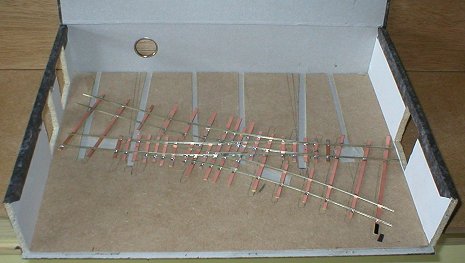
 This is the basic
boxfile with track placed in to get an idea of how things will work. I
have cut some 3mm thick MDF to shape and allowed slots for wiring and
point operation.
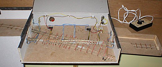
This is the basic
boxfile with track placed in to get an idea of how things will work. I
have cut some 3mm thick MDF to shape and allowed slots for wiring and
point operation.
The ends have also been cut to allow access to the fiddle yard. I was surprised that apart from the spine, they are all thin chipboard. Cutting was with a piercing saw and a round blade tidied up with emery sticks.
Track (built by my dad, Brian, because he is better at track than me) is scratchbuilt using SMP parts and is two of the smallest Y-points. The front of the box will be re-attached with two hinges later.
Points are operated with rods made from K&S brass strip. A pin sticks up through the tie bar and at the other end is the metal parts of an electrical "chocolate block" which will allow me to attach and remove the operating knob which will stick through the spine of the box.
Pins soldered through the strip will work micro switches to change the polarity of the point frogs. If you used Peco points, this wouldn't be necessary as they sort out their own electrics.
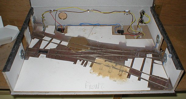
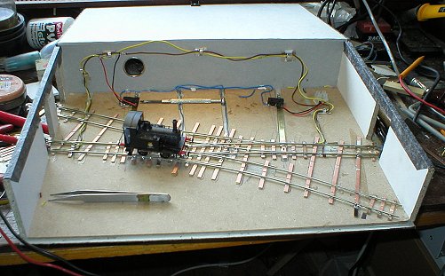 The first train runs!
A K's Y8 is the idea test loco as it is very short and this stalls at the nearest hint of electrically dead rail. The track has been glued down and point rods fitted.
Controller wiring hadn't been done at this stage so a couple of wires from an H&M did the job.
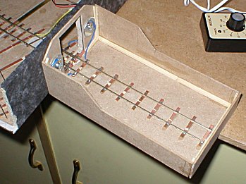
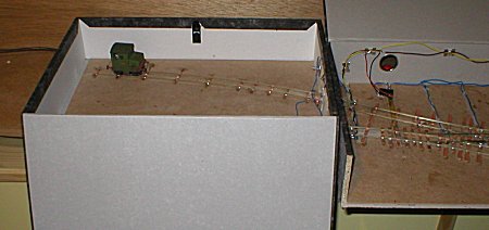 The fiddle yard is
another file with an MDF base. Track has been extended over. Power is
transferred through the bolts that hold the "boards" together.
The flap is held up with a wooden dowel to hide the contents and maintain the sense of mystery.
The fiddle yard is
another file with an MDF base. Track has been extended over. Power is
transferred through the bolts that hold the "boards" together.
The flap is held up with a wooden dowel to hide the contents and maintain the sense of mystery.
 At
the other end, the track extends into an extension tube. This can be packed
in the fiddle yard when not required - as allowed for in the rules.
At
the other end, the track extends into an extension tube. This can be packed
in the fiddle yard when not required - as allowed for in the rules.
By this stage the wiring was in for transformer and controller which can be unplugged for transport. All of this is hidden by the buildings.
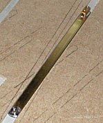
 Close up of the extension
tube made of the remains of the MDF I lined the bases with. I've had to
lop a bit off the top to get it to fit in the fiddle yard.
Close up of the extension
tube made of the remains of the MDF I lined the bases with. I've had to
lop a bit off the top to get it to fit in the fiddle yard.
Thin MDF cuts nicely with a Stanley knife and steel ruler, a bit like cardboard modeling. Mind you, more cuts are required but the result is stronger. PVA glue joins are braced with stripwood as didn't want anything coming apart in transit.
You can clearly see the bolts holding the "boards" together which also transfer track power. Cheapo DIY ones were used which turned out to be a mistake as the wires refuse to stay soldered to them. Not a problem in the yards but inside the buildings, access is very limited for repairs. I'd recommend sourcing some proper brass fittings if you are trying this.
The track has been sprayed with primer and then track-colour from Precision paints aerosol. Card inserts are being stuck in to bring the ground up to the level of the top of the sleepers. Ballasting experiments have also begun. The top one uses traditional sawdust with watered down PVA. The bottom uses the same stuff but the glue was painted onto the card/sleepers. Tradition has won out here !